|
|
|
|
|
|
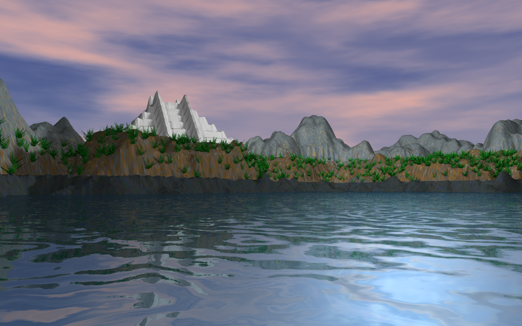
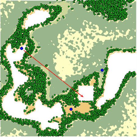
El Dorado model terrain above, created from a painted floorplan heightfield. Landscape by Genesis Toolkit using the GT interface, to distribute plants with all scene scripts auto-generated. Final image script execution by POV-Ray raytracing renderer produced the displayed image. |
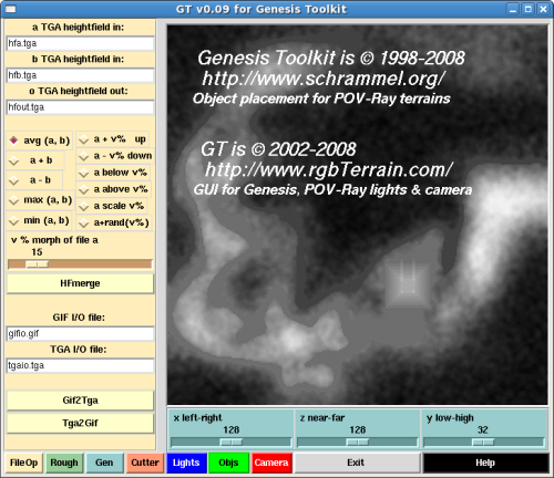
GT v00.09
Make terrains natural with a powerful object distribution control deck.
|
GT for Genesis Toolkit development release.
No permission granted for any of the following:
Please do create with GT! GT for Genesis Toolkit © 2008
|
|||||||||
| top | |||||||||||
|
Application and settings
selectors below GT main screen. - Objs is a reserved function. - Exit terminates GT. - Help is this document. Click a selector button below to see the control panel, click anywhere on that control panel to come back. |
Overview
GT is a control panel for the Genesis Toolkit utilities. Linux and Windows downloads are here. This toolchain is most widely used for distributing objects onto terrain for a natural landscaped presentation. Tools include file operations, altitude and distribution, scaling and optimization, camera and lights placement. |
|
|||||||||
|
|
|||||||||||
| top | |||||||||||
|
Genesis Tookit
is available at schrammel.org. Windows version, just install. Linux version, requires the following libraries in /lib or /usr/lib with sym links; sym link: /lib/ld-linux.so.1, to file: /lib/ldlinux.so.1.7.14 sym link: /lib/libc.so.5, to file: /lib/libc.so.5.3.12 sym link: /lib/libm.so.5, to file: /lib/libm.so.5.0.8 Equivalent libraries for your Linux distribution should be available at rpmfind.net. |
Pre-install requirements
GT requires Genesis Toolkit and pre-installed utilities:
|
Tcl/Tk POV-Ray ImageMagick Firefox |
www.tcl.tk povray.org imagemagick.org firefox.com |
||||||||
| Linux install
Download: gt0009.tar.gz
From the console, unpack: tar -xzf gt0009.tar.gz
Change to the directory: cd gt00.09
Make gt.tcl executable: chmod 774 gt.tcl
Run: ./gt.tcl
|
|
Windows install
Download: gt0009.zip
Unpack, right-click: gt0009.zip
Choose: Extract All
In Extraction Wizard, click: Next, Next, Finish
Double-click gt0009 folder. Run, double-click: gt.tcl
|
|||||||||
|
"GT fast". © 2008
Graphics and Engineering art (at) rgbterrain.com
|
|||||||||||
| top | |||||||||||
|
File operations
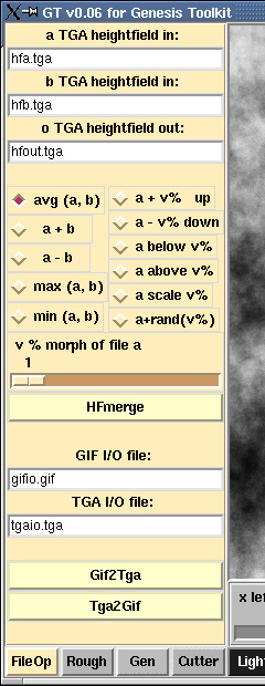
File operations controls are selected at the lower left. Action buttons in each application group are colored a little hotter. In File ops, these are: - HFmerge, - Gif2Tga, and - Tga2Gif. HFmerge To merge two .TGA heightfields, enter source and target filenames in the FileOps control panel data entry fields. Then, select left-column radio-button method to merge data in files a and b: - avg(a,b) average, - a+b or a-b add or subtract, - max(a,b)or min(a,b) maximum or minimum. or Select right-column method to morph data only in file a: - a+v% or a-v% stretch or squash, - a below v% or a above v% truncate, - a scale v% or a+rand(v%) linear or random scale. Then click HFmerge. Gif2Tga and Tga2Gif For translation between .GIF and .TGA, enter I/O filenames in the corresponding fields prior to clicking Gif2Tga or Tga2Gif. File operations controls are colored manila yellow. |
||||||||||
| top | |||||||||||
|
Rough application
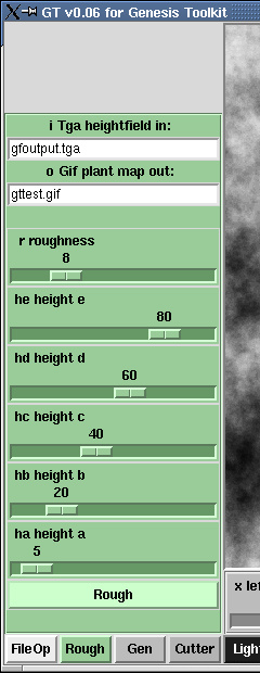
Rough application controls are selected at the lower left. Data entry fields expect: - the name of a .TGA heightfield file you provide, and - a name you specify for a .GIF file to be created by Rough. .TGA heightfield is the same one used by you in POV-Ray, for terrain shape. .GIF file created by Rough may be used as a POV-Ray image_map applied to your terrain shape. Repainting first is also allowed. The roughness control inversly specifies the probability that objects will appear on the terrain. Imagine increasing the roughness of terrain. Height controls define the edges of topological mapping altitude regions, to be used during object generation. |
||||||||||
|
Click the brighter Rough button to create the topological map,
or regenerate the topo map after further adjustment.
Rough application settings are also used by the object generator, Gen. See the Rough output display, to to the right. Rough application controls are soft green. |
|
||||||||||
| top | |||||||||||
|
Gen application
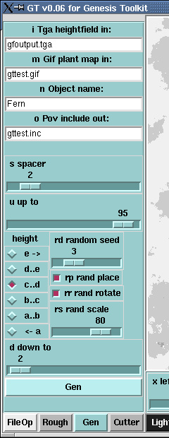
Gen application controls are selected at the lower left. Data entry fields expect: - the name of a .TGA heightfield file you provide, - the name you specified for the .GIF file created by Rough, - a name you specify for objects created by Gen, and - a name you specify for the POV-Ray include file to be created by Gen. To repeat the Rough application notes, the .TGA heightfield is the same one used by you in POV-Ray, for terrain shape. Spacer controls the amount of space between objects. Up to is maximum, and Down to is minimum altitude for objects. These controls bracket the height radio buttons. Height radio buttons: choose one to populate that band of topology with the objects Gen creates. Flip back to the Rough control panel for reference. Random seed selection gives various repeatable object distributions. Random place may be turned off to get regular grid placement. Random rotate may be turned off to get no object rotations. Random scale creates objects of different sizes, constrained by this lower percentage factor. |
||||||||||
|
Click the brighter Gen button to create the POV-Ray include file,
or regenerate that file after further adjustment.
The POV-Ray files are parsed and used for a refreshed display of Gen-created objects, with Camera and Lights. See the Gen output display, to the right. Gen application controls are frost blue. |
|
||||||||||
|
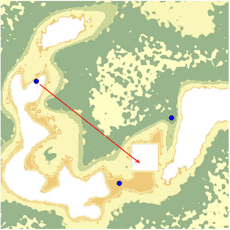
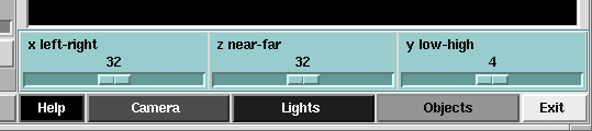
Below the map, x, z, and y sliders align Gen objects to
the dimensions of your POV-Ray model terrain.
These control settings are retrieved from POV-Ray include file
camera.inc.
Activate Camera or Lights to unlock these controls for adjustment. Click Done to synchronize new settings within camera.inc and camera.pov files. |
|
||||||||||
| top | |||||||||||
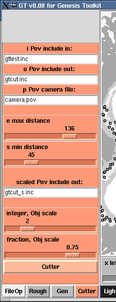 |
Cutter application
Cutter application controls are selected at the lower left. The first data entry field expects the name of the POV-Ray include file already made by Gen - the objects. The second data entry field expects the name of the POV-Ray include file to be made by Cutter - the optimized objects. The third data entry field is filled by the camera.pov stub file made by saving the Camera or Lights settings. Cutter uses the camera parameters in camera.pov. Sliders adjust max and min distance for object optimization, by eliminating object features not present within the adjusted window. Reducing the number of objects to be processed optimizes POV-Ray rendering. Camera parameters define the cone. Then objects beyond max distance are eliminated. All objects surrounding the camera within min distance sphere radius are preserved. The final data entry field is filled by the name of a POV-Ray include file to be made after Cutter, containing the scale-adjusted objects. Sliders adjust integer and fraction parts of growth or shrinkage. Entire object population size is adjusted, while preserving Gen proportions. |
||||||||||
|
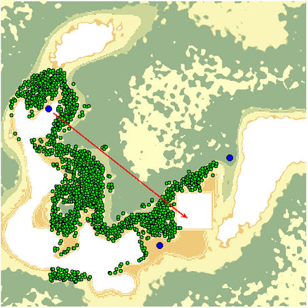
Click the brighter Cutter button to create the POV-Ray include files,
or regenerate those files after further adjustment.
The POV-Ray files are parsed and used for a refreshed display of Cutter-selected objects, with Camera and Lights. See the Cutter output display, to to the right. Cutter application controls are autumn orange. |
|
||||||||||
| top | |||||||||||
|
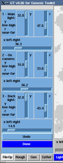
Light settings
Light setting controls are selected below the map area. Initial Light positions are retrieved from camera.inc values. - Light 1 is main, - Light 2 is on camera, and - Light 3 is back. The naming convention (main, on camera, and back) is meant to emulate classical photographic lighting, and helps keep setup easy... but you do not have to "follow the rule". Blue circle "Lights" fly around the map, while adjusting the sliders for Light positions. This action provides very quick setup of the POV-Ray lights. As of this GT version, there is no similar visual feedback for the y (low-high) adjustments, except to just render. Light setting is modal - you must acknowledge Done to leave the control panel... then camera.inc and camera.pov files are written. This action provides Undo capability. Light setting controls are blue. |
||||||||||
| top | |||||||||||
|
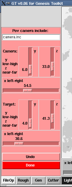
Camera settings
Camera setting controls are selected below the map area. The data entry field expects the name of a POV-Ray include file. This file contains initial Camera and Light positions, plus Scale factors. Default file "camera.inc" is provided, with instructions. Initial Camera positions are retrieved from camera.inc values. A red arrow "Camera" flies around the map while adjusting the sliders for Camera and Target positions. This action provides very quick setup of the POV-Ray camera. As of this GT version, there is no similar visual feedback for the y (low-high) adjustments, except to just render. Camera setting is modal - you must acknowledge Done to leave the control panel... then camera.inc and camera.pov files are written. This action provides Undo capability. Camera setting controls are red. |
||||||||||
| top | |||||||||||
| All content © 2008 Graphics and Engineering |